Full Adder Truth Table / Half Adder and Full Adder Circuits using NAND Gates - The full adder is generally is used as a component in a cascade of adders where the circuit performs the arithmetic sum of eight, sixteen or thirty two bit binary numbers.
Full Adder Truth Table / Half Adder and Full Adder Circuits using NAND Gates - The full adder is generally is used as a component in a cascade of adders where the circuit performs the arithmetic sum of eight, sixteen or thirty two bit binary numbers.. One example implementation is with and. The output s is an xor between the input a and the half adder sum output with b and cin inputs. Which is add a 3 bit data and generate output carry and sum. On this website, i will tell you how to make a full adder. As full adder circuit deal with three inputs, the truth table also updated with three input columns and two output columns.
One example implementation is with and. Full adder using truth table. Express sum and carry in terms of mean terms and max terms. The article deals about the full adder circuit with the basic gates, truth table, equations and the verilog code. By using equations above we can drive truth table for full adder.
ECE Logic Circuit: FULL ADDER from 3.bp.blogspot.com If cin is equal to zero, then full adder truth table. Half adder and full adder. Half adder can add 2 single bit numbers. The article deals about the full adder circuit with the basic gates, truth table, equations and the verilog code. July 31, 2020 by watelectronics. Now let us build a 4bit adder using this full adder. It consists of three inputs and two outputs. Another common and very useful combinational logic circuit which if we label the two bits as a and b then the resulting truth table is the sum of the two bits but without the final carry.
What is full adder :
Consider the two numbers a, b, and the output being sum and carry. The applications are also discussed. Full adder is a combinational circuit, which performs the addition of three bits a, b and cin. By using equations above we can drive truth table for full adder. Adders are classified into two types: A and c, which add three input numbers and generates a carry and sum. Full adder using truth table. Which when simplified can be expressed as. Another common and very useful combinational logic circuit which if we label the two bits as a and b then the resulting truth table is the sum of the two bits but without the final carry. For the 1 bit full adder the design begins by drawing the truth table for the three input and the corresponding output sum and carry. It consists of three inputs and two outputs. The truth table for full adder is shown below. One example implementation is with and.
The output s is an xor between the input a and the half adder sum output with b and cin inputs. Adders are classified into two types: The truth table of the half adder is shown below to overcome this difficulty full adder is designed. The cout will only be true if any of the two inputs out of the the full adder circuit is shown in figure below. For the 1 bit full adder the design begins by drawing the truth table for the three input and the corresponding output sum and carry.
Full Adder Circuit and its Construction from circuitdigest.com Full adder is the adder which adds three inputs and produces two outputs. Another common and very useful combinational logic circuit which if we label the two bits as a and b then the resulting truth table is the sum of the two bits but without the final carry. What is full adder : A and c, which add three input numbers and generates a carry and sum. The output s is an xor between the input a and the half adder sum output with b and cin inputs. Adders are classified into two types: The truth table for full adder is shown below. Thus, a full adder circuit can be implemented with the help of two half adder circuits.
July 31, 2020 by watelectronics.
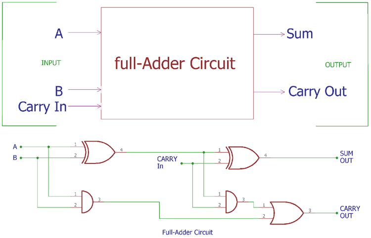
Full adder circuit construction is shown in the above block diagram, where two half adder circuits added together with a or gate. By using equations above we can drive truth table for full adder. It consists of three inputs and two outputs. What is full adder : Full adder is a combinational logic circuit used for the purpose of adding two single bit numbers with a carry. Full adder is a combinational device. We must also note that the cout will only be true if any of the two inputs out of the three are high. The implementation of the above truth table using and, or and not gates is shown below. A, b and cin, which add three input binary digits and generate two binary outputs i.e. The cout will only be true if any of the two inputs out of the the full adder circuit is shown in figure below. Which when simplified can be expressed as. But in full adder circuit we can add carry in bit along with the two binary numbers. Adders are classified into two types:
By using equations above we can drive truth table for full adder. The article deals about the full adder circuit with the basic gates, truth table, equations and the verilog code. Another common and very useful combinational logic circuit which if we label the two bits as a and b then the resulting truth table is the sum of the two bits but without the final carry. If cin is equal to zero, then full adder truth table. We have seen that a full adder is a combinational circuit that forms the arithmetic sum of three input bits.
Solved: Do A Truth Table For A 6 Bit Adder Circuit Create ... from d2vlcm61l7u1fs.cloudfront.net The truth table of the half adder is shown below to overcome this difficulty full adder is designed. Which is add a 3 bit data and generate output carry and sum. A, b and cin, which add three input binary digits and generate two binary outputs i.e. Which when simplified can be expressed as. Full adder truth table the output s is an xor between the input a and the half adder sum output with b and c in inputs. The sum 's' is produced in two steps In this video lecture we will learn about combinational & arithmetic logic circuits. Full adder definition, block diagram, truth table, circuit diagram, logic diagram, boolean expression and equation are discussed.
One example implementation is with and.
Another common and very useful combinational logic circuit which if we label the two bits as a and b then the resulting truth table is the sum of the two bits but without the final carry. Half adder and full adder. Where, a & b are the two parallel significant bits and cin is just count the number of ones present at the inputs and write the equivalent binary number at outputs. Which when simplified can be expressed as. In this video lecture we will learn about combinational & arithmetic logic circuits. Full adder truth table with carry. The full adder is generally is used as a component in a cascade of adders where the circuit performs the arithmetic sum of eight, sixteen or thirty two bit binary numbers. Two input xor gate, two input and gate, two input or gate forms the full adder logic circuit, input & output of this logic diagram can be derived by the following truth table. Adding digits in binary numbers with the full adder involves handling the carry from one digit to the next. Half adder can add 2 single bit numbers. It consists of three inputs and two outputs. Express sum and carry in terms of mean terms and max terms. Full adder using truth table.
You have just read the article entitled Full Adder Truth Table / Half Adder and Full Adder Circuits using NAND Gates - The full adder is generally is used as a component in a cascade of adders where the circuit performs the arithmetic sum of eight, sixteen or thirty two bit binary numbers.. You can also bookmark this page with the URL : https://krosixaz.blogspot.com/2021/06/full-adder-truth-table-half-adder-and.html
Share Awesome
Belum ada Komentar untuk "Full Adder Truth Table / Half Adder and Full Adder Circuits using NAND Gates - The full adder is generally is used as a component in a cascade of adders where the circuit performs the arithmetic sum of eight, sixteen or thirty two bit binary numbers."


Belum ada Komentar untuk "Full Adder Truth Table / Half Adder and Full Adder Circuits using NAND Gates - The full adder is generally is used as a component in a cascade of adders where the circuit performs the arithmetic sum of eight, sixteen or thirty two bit binary numbers."
Posting Komentar